
Carry a changed opening or insert through the formwork drawing, plywood cut list and physical part identification. Compare the affected parts with the current detail so the right replacement or revised component reaches its intended location.
PanelSource supplies film faced shuttering plywood and custom-size plywood parts from the current supply drawings. Share the changed detail and affected parts first; we help update the plywood, machining and order quantities.
Choose the plywood supply for your next step
- Use film faced shuttering plywood when the revised work calls for full sheets to be processed by your fabricator.
- Use custom-size plywood parts for revised openings, handed pieces and identified replacement parts.
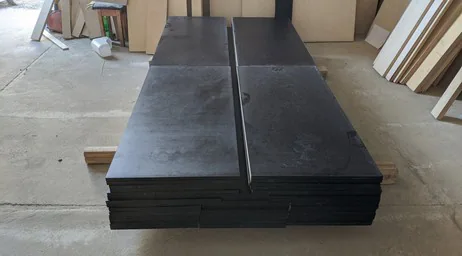
- Where the changed component specifies a black 18mm facing, compare 18mm black film faced plywood with the required construction and revised geometry.
Establish which drawings govern each decision
Permanent-works drawings define the concrete structure and its requirements. Formwork drawings define how the temporary system will form and support it. Fabrication drawings and cut lists translate relevant details into components. Each has a role; one attractive drawing does not automatically replace the others.
The ACI 347R formwork guide excerpt discusses contract information, drawings and coordination of openings and embedded items. It also distinguishes responsibilities for the permanent structure and formwork.
Create a current drawing register for the affected area, including revision and issue date. State which document controls geometry, finish details and temporary support. Resolve conflicting dimensions through the responsible project team before the affected fabrication proceeds.
Check datums, faces and handedness before locating a feature
Locate an opening from defined reference edges or project datums. Identify the elevation and which side the drawing shows. A view from the concrete side can reverse a feature compared with a view from behind the formwork.
For repeated components, give mirrored parts different identifiers where their orientation matters. Mark the concrete-contact face and required panel direction on the fabrication information. Do not rely on the installer recognising a nearly symmetrical hole pattern.
Also distinguish the opening in the finished concrete from the size of a box-out or liner used to create it. Those dimensions can differ because of the detail. The workshop needs the actual component dimensions, not an assumed conversion from the architectural opening.
List the interfaces touched by the change
A change should name the connected items, not just the plywood sheet. This short matrix helps direct questions to the appropriate drawing or responsible party.
| Changed feature | Connected information | Question to resolve |
|---|---|---|
| Service opening | Structural geometry, reinforcement and box-out detail | Is the revised position coordinated across those requirements? |
| Cast-in item | Item orientation, fixing method and installation access | Can it be located and retained as designed? |
| Tie or support position | Temporary-works design and adjacent components | Does the designer need to revise the arrangement? |
| Visible joint or recess | Concrete elevation and appearance reference | Will the finished pattern still match the requirement? |
| Panel outline | Cut list, connections and neighbouring parts | Which existing parts remain usable without alteration? |
The matrix identifies questions; it is not permission to move structural or temporary-works components.
Trace one relocated opening through the package
Consider an opening moved after plywood pieces have been cut. First identify the affected wall zone and obtain the coordinated change information. Compare the revised feature with the current part drawing, support layout and adjoining details.
Next identify the physical pieces: uncut sheets, finished parts, packed components and installed panels are different situations. Determine which can remain as supplied and which require replacement or a specifically agreed alteration. Do not count every part carrying the old revision as scrap without checking its actual geometry.
Finally issue the revised part schedule and record the disposition of the affected pieces. The crew should be able to determine which component belongs in the changed position without reconstructing a chain of messages or comparing unlabeled photographs.
Coordinate the revised geometry with the formwork design
A moved opening may look like a simple machining adjustment, yet intersect a connection or change the supported panel area. A dimensionally accurate replacement is not automatically a structurally acceptable replacement.
HSE's temporary-works guidance emphasises planned management, appropriate design and checking, and preventing other work from compromising temporary works. For a project change, establish whether the responsible designer must revise the system or its instructions.
Do not solve a clash by moving a tie, cutting a support or changing a connection based only on a site photograph. Identify the proposed alteration, relevant loads and affected components through the project's change procedure.
Keep physical parts identifiable as revisions change
Mark parts in a way that preserves the intended concrete finish. Retain the part identifier when a component moves between the workshop, packing area and installation zone. Keep superseded instructions away from the active fabrication set.
If a piece is altered under the agreed method, update its identification and inspection record. A corrected drawing with an unchanged packing label can still send the wrong component to the workface.
Our formwork fabrication guide covers the cut list, first-piece check and machining details that need to follow that revision.
Use digital models to communicate, then verify the issue
A coordinated model can make clashes and spatial relationships easier to understand. It still needs an identifiable issue, dimensions and an agreed connection to fabrication information. A screenshot without revision or scale is a weak instruction for machining a component.
Keep planning information and custom components connected through the formwork workflow. Use consistent drawing revisions, part references and installation details whether the project uses models or dimensioned drawings.
Record which issued information generated the cut list. When a model changes, confirm whether the exported drawings and part files also changed; do not assume automatic synchronisation.
Close the change with location and quantity records
Check that the revised quantity, part identifiers and installation zones agree. Record replaced or altered pieces and remove obsolete parts from the intended installation set. Retain the reason for the change with its drawing reference.
For our panel supply, start with the changed detail and affected parts. We help develop the custom-size requirements and processing, then add quantities and destination. Tell us whether the enquiry replaces an earlier schedule or adds to it.
Carry the current drawing and affected order lines into the quotation. We update the panel supply details while the project team resolves the formwork design and installation requirements.
Plywood supply questions
Can an enquiry cover only the changed parts?
Yes. Identify the affected part references and current drawing, and state whether the new quantities replace or add to an earlier schedule. Unchanged parts can keep their existing references.